Monday, November 21, 2011

Laser-Toast - Probably the Best CAD-CAM'ed PBJ Sandwich Ever...

Close-up of the top laser-toasted bread slice...


A fandango food folly, of sorts... Here a laser-cutter was used to cut/ etch - toast - some slices of bread for a Peanut-Butter & Jelly Sandwich... Each of the sandwiches slices is divided into twelve, numbered and matched, 'bites'. Each bite includes corresponding, same size, cavities into that secure that equal quantities of both peanut-butter and jelly are distributed into each of the numbered bites. The cavities of the middle slices are misaligned in comparison to each other to make sure the won't mix and become too gooey before the mastication phase... A number of different cutting settings were used to create a variety of bespoke cuts across the toast planes. The 'toasting' patterned (wave-like) cuts are dense and shallow; the 'bite' cuts are a bit deeper to allow for each of the twelve bite segments to break off; and the cavities for the peanut-butter and jelly have been cut all the way through...

The laser-cut Peanut-Butter & Jelly sandwich was the best ever Buildware (CAD-CAM) made sandwich I've ever had..! 


Top, left to right: Top Slice, Top-Middle-Slice, Bottom-Middle-Slice, Bottom Slice...

Exploded view of the PBJ Sandwiches layers...

Top and bottom sides of the assembled PBJ Sandwich...

The cavities of the middle-slices are misaligned in comparison to each other, thus assuring an equal quantity of both peanut-butter and jelly in each bite...

A number of different settings were used to allocate different types and depths of cuts across the toast planes...

Each numbered 'bite' breaks off easily from the PBJ Sandwiches main body...

A sequential breakdown of the CAD-CAM PBJ Sandwiches 'bites'...

The assembled CAD-CAM PBJ sandwich...

Close-up of the Bottom Slice...

A short movie showing the making of the CAD-CAM PBJ Sandwiches Top Slice...

Thursday, November 17, 2011

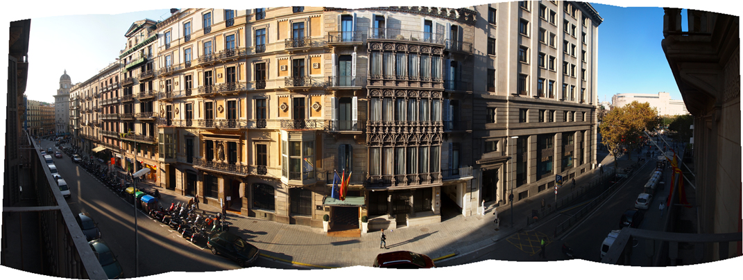
Hotel Room Views...

Barcelona, Spain 

Helsinki, Finland 

 Celebration, Florida 


Luxembourg, Luxembourg 

Amsterdam, Holland 

Seoul, Korea

Tuesday, November 1, 2011

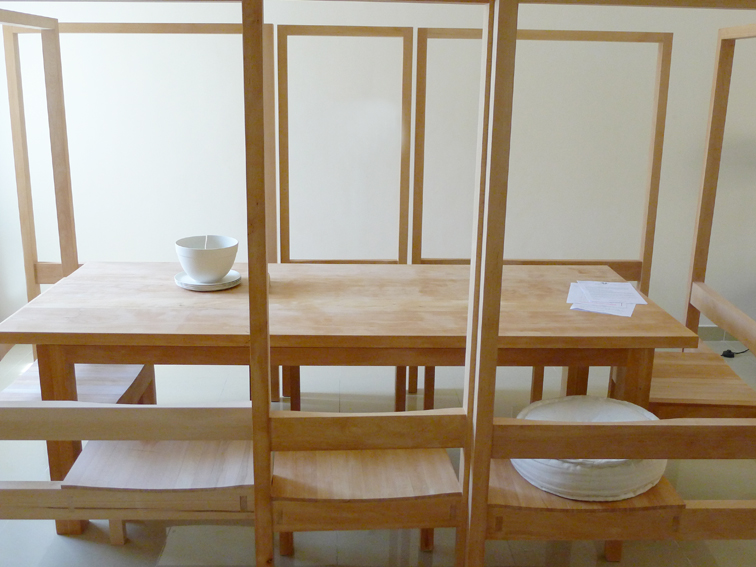
The Testudo Dining Set/ Space...

 The set's Left chair...

Initially designed almost two decades ago during my Senior year at Parsons, the Testudo Dining set/ Space (AKA the Turtle Dining Set) has finally been realized. The design, which in this rendition consists of eight  high-backed chairs around a table, was perhaps partly inspired and named after the Roman battle formation Testudo (Turtle in Latin) where individual units (in this case chairs) are positioned in a 'wrapping' formation around a core (a table), thus defining a space. The dining set is intended for large open interiors, where it can provide its own kind of intimacy/ framed space by its set-up alone... 

Four different chair types - each repeated twice -  are needed to complete the design. These are the Left & Right Chairs, the Middle Chair and the End Chair, which are placed around the rectangular table. All the pieces were made of solid beech (bok in Swedish, pyƶkki in Finnish). The completed design has a wax finish... 

The design has gone through a number of iterations since its conception, involving a major overhaul during our time in London as Small Architecture (nowadays Independent Architects) when its current frame based formation was developed (it used to be much more solid before). This, in turn, needed to be further tweaked (mainly it proportions and dimensions) to enable it to be fabricated locally... 

The fabrications required its fair share of supervision, toing & froing with the carpenters regarding the details, and we (well, Maysaa) did the final (Finland sourced) waxing of the set, but we're very happy with the end result... 


 The Turtle Dining Set & Space...

The End Chair... 

The Right Chair... 

The Middle Chair... 

 The, roughly 100 kilogram, solid beech table...


Above & below - close-ups of some of the details... 


The beech table and seat planes...


 Following up and inspecting a prototype  at the factory...

 Junior furniture tester determining the seat's comfort coefficient...

A bamboo pulp bowl and set of plates from Holland, an Iittala glass dispenser, and a kuksa, are framed by the Testudo chairs... 


A short, still a bit raw, animation made during the development of the design...

Tuesday, October 25, 2011

Meat & Bone Vases and Bowls...


A few additional examples from the Meat & Bone series - where the usually discarded/ removed, but in its own right quite strong (if brittle) and beautiful, FDM support material is allowed to perform the role of a protagonist in the final design. Also, as in the previous submissions, here the different software based settings for distributing the supports are used as design components, i.e. the 'white bits' (made of ABS plastic) are distributed and the supports are allowed to 'grow' up to brace them - consequently the somewhat funky shapes of the brown bits...

An additional engaging quality about these designs is that, in a way, they openly acknowledge, even celebrate a bit, the slight degrees of unpredictability and randomness, even 'imperfections' (in a wab-sabi sort of way) of the digital fabrication processes, which still all too often are considered as almost faultless - 'we can make almost anything' - kinds of machines/ fabricators... These designs aim not to do that, but instead take a step back, and try to recognize the true material, sensory (textural, aural, olfactory, proprioceptive, etc.) digital & virtual, thrills and seductive qualities affiliated with making things through the various Buildware/ CAD-CAM processes... 

More related submissions to come in the future...


 The Meat & Bone (M&B/ MaB) Castle Vase...

The CAD (Catalyst Ex 4.2) version of the Castle Vase...


 The MaB Wing-Commander Vase/ Bowl...


The MaB Ring Bowl... 


Sunday, October 16, 2011

Book-Corner-Seat...


A while back we moved to a new, slightly bigger, residence here in Qatar. We decided to rent it unfurnished as, quite frankly, the furniture the landlord was proposing to give us looked like something from Liberace's SM chamber... Consequently we decided to (along with buying some of the more necessary pieces such as mattresses, living room sofas, etc. immediately) design a number of bespoke pieces ourselves... After extensive searching for a decent carpentry shop, we finally found one in the old industrial area which seemed to be both willing and able to produce something from the materials we defined, and according to the standards and level of detail we expected... After a number of false starts and prototypes we finally received our first set of furniture a short while back... We're very happy with the results...

This initial piece featured is the Book-Corner-Seat, which was designed for the landing on our top floor. It, as its name suggest, sits in the corner of the landing which is flanked by entrances to our bedrooms, and provides a focal point, as well as a casual, bit more private, 'hang-out' place where to read, chat or daydream... We're in the process of getting a thin cushion made for the square seating area... 

Included below are some additional images of the design, as well as its buildware prototype, in action...  

More related furniture submissions to come in the future... 


Sunday, October 9, 2011

Design Details No. 03 - Lego Building Instructions...


During a recent trip to Copenhagen I bought a Lego rendition of the Farnsworth House - something I suspect I did probably more for myself than my children... What was interesting, however, was that the completed build, which was finely assembled by my architect wife and youngest daughter, was perhaps less engaging than the instructions outlining the assembly process of the Lego house. Having spent countless hours over traditional paper-based construction drawing (plans, elevations, sections), these Lego building construction instructions, with their narrative format and axonometric views providing a sequential step-by-step breakdown and timeline of the builds various stages, were a very suggestive revelation for how a different set of, even more complex and multifarious designs, could potentially be dealt with and explained...

How could these kinds of inforgraphics-esque sequences of instructions be applied in the clarification of various script based design conceptions (Grasshopper, GC)? How could they be used, through an ipad or its like, as a means for conveying dynamic construction drawings on site? Could these kinds of, much clearer and intuitively understood, illustrations be used to describe both the more technical (structural, mechanical, electrical, services, etc.) components as well as the more pictorial and conceptually explanatory (shown to clients & colleagues) types of 'drawings' (& animations) be used to turn today's construction-drawings into a more accurate and more easily implementable format reflective of the more recent developments used to conceive pieces of architecture..?

There's much to muse about...


 Stages 10 (above, above) and 27 (above) of the assembly process...

 The Completed Lego build of the Farnsworth House...


All drawn illustrations sourced from the instruction booklet accompanying the Lego building...